Hypertuning my CGEM II Tracking Mount
In early January I developed what seemed to be a head cold and soon after tested positive for COVID-19. In the process of assembling my funeral pyre, I experienced the extreme disappointment of overcoming my symptoms and being left with a completely free 2-week period off work.

Luckily in mid-December I had also ordered a modification kit for my astrophotography mount and it happened to be delivered a day before my quarantine began. As I write this I am near the end of my isolation and the biggest lesson I’ve learned so far is that I should have moved my coffeemaker into my office a long time ago because it is saving me from making so many trips downstairs. I would have thought that a surprise 2-week vacation would mean marathon imaging sessions for as long as the clear skies would allow, but I still have quite the backlog of previous images yet to work on, so I ended up staying inside and tinkering with my tracking mount. Or in other words, I caught COVID and decided to spend my time off tricking out a giant fidget spinner.
What is Hypertuning?
Astronomy mounts need to track in a precise manner to counteract the rotation of the Earth and keep a given nebula or planet targeted in the telescope. For visual use tracking doesn’t need to be as precise and some periodic error (a slow oscillation of the target back and forth over a period of several minutes due to mechanical imperfections) is acceptable, but for long exposure astrophotography the tolerances are much less compromising. The problem is no tracking mount is flawless, though some are certainly better than others. Regardless of the specific mechanics at work, machined gears and other components tasked with providing continual and smooth movement against the 460 m/s rotation of our Pale Blue Dot will never be perfect. Along with this, the factory assembly of these tracking platforms often prioritizes quantity over quality, meaning some of the moving parts may be too close together, too far apart, under or overlubricated, or simply made of substandard material.
Hypertuning reduces these imperfections through various means, and for the CGEM it involves sanding down some components for a better fit, re-application of lubricants, and replacing some components with smoother, lower-friction options. Or in other words, its the Pimp my Ride of telescope mounts, except the before and after pictures look rather boring because all of the changes are internal.

I am whelmed.
You can perform Hypertuning on your own but it is a lot easier with the purchase of a DIY kit from Ed via the website Deep Space Products. The kit includes low-friction replacement parts, lubricants and polishing compound, most of the necessary tools to perform the modifications, and of course the instructions. DIY kits are also available for some similar mounts like the Orion Atlas.
I really had no idea what I was getting myself into but I trusted the instructional videos (which total about 3 hours, at least for the CGEM modifications) would compensate for any lack of knowledge on my part. Or if I felt in over my head I reasoned I could at least safely reassemble anything I had taken apart without too much effort. Ed does offer the Hypertuning service if you ship the mount to him, and this may be a better option for anyone hesitant to disassemble an expensive piece of equipment.
I wanted to write up my experience with Hypertuning because it can be a daunting task, and I think the only reason I was comfortably able to accomplish it was due to having several days off with no distractions. Along with this, finding reviews, recommendations, or generally any written experiences regarding niche topics like this (outside of digging through pages of Cloudy Nights forum entries from 2009) can be difficult, so if my writeup here gives sufficient context to another considering this process then it will have served its purpose. I should probably disclaim that the little experience I have is limited to the CGEM II mount and can’t speak to the difficulty or complexity in completing similar modifications to other models.
The Benchmark
Before the Hypertune my CGEM was lacking in tracking performance. My autoguiding correction in PHD2 (if you are unfamiliar with guiding, please see the FAQ page on Equipment for a short explanation) routinely averaged out at around 2.5 arcseconds but could often spike near 6, and both Right Ascension and Declination axes experienced sporadic periods of over or under correction. This indicated some issues with backlash, meaning some of the gears were poorly meshed. If the guidestar began drifting in a certain direction, the mount could correct for it, but if this correction then caused a slightly drift in the opposite direction, reversing the movement of the gear would not impart an immediate movement in the mount itself due to the excessive space between the gear teeth. Considering I shoot at a relatively short 350mm focal length (meaning my photos have a field of view several times the apparent width of the Full Moon), this amount of error was small enough to not affect most of my photos, but could stand some improvement.
It’s not 2.3, its 15,000
However, I had also noticed a more recent problem in the Declination tracking where the guidestar would would suddenly jump over a dozen arcseconds or more, and this was imparting visible elongation of the stars in my photos. I had a bad habit of slewing the mount back to the home position before shutdown each morning and this problem was occurring more frequently in colder conditions, so I suspect my inadvertent use of only one section of some of the gears may have reduced the lubrication in those sections over time until it compromising the tracking performance.
To sum up, though the CGEM is by no means the last mount I every intend to buy, Hypertuning was the best solution to maximizing the capability of my current mount without spending well into 4 figures on a higher-tier platform (….yet).
Day 1: Teardown & Cleaning
The first major step is a complete disassembly of the mount. This was probably the slowest going for me since there is a Celestron technician somewhere who loves using threadlocker. Many of the most external locking nuts or sealing bolts covering the bearings (in other words, the components preventing access to all the rest) use small 2mm set screws or spanner heads which may be incredibly difficult to loosen, though the DIY kit includes a custom tool which is quite helpful for extracting a particular deep-seated locking ring. For the rest, a heat gun, periodic application of WD40, and liberal use of a screw extractor drill bit during a fit of blind rage was enough to remove them, but there were casualties. Fortunately, the M4x4mm set screws are very cheap and the replacements should arrive in a couple days.
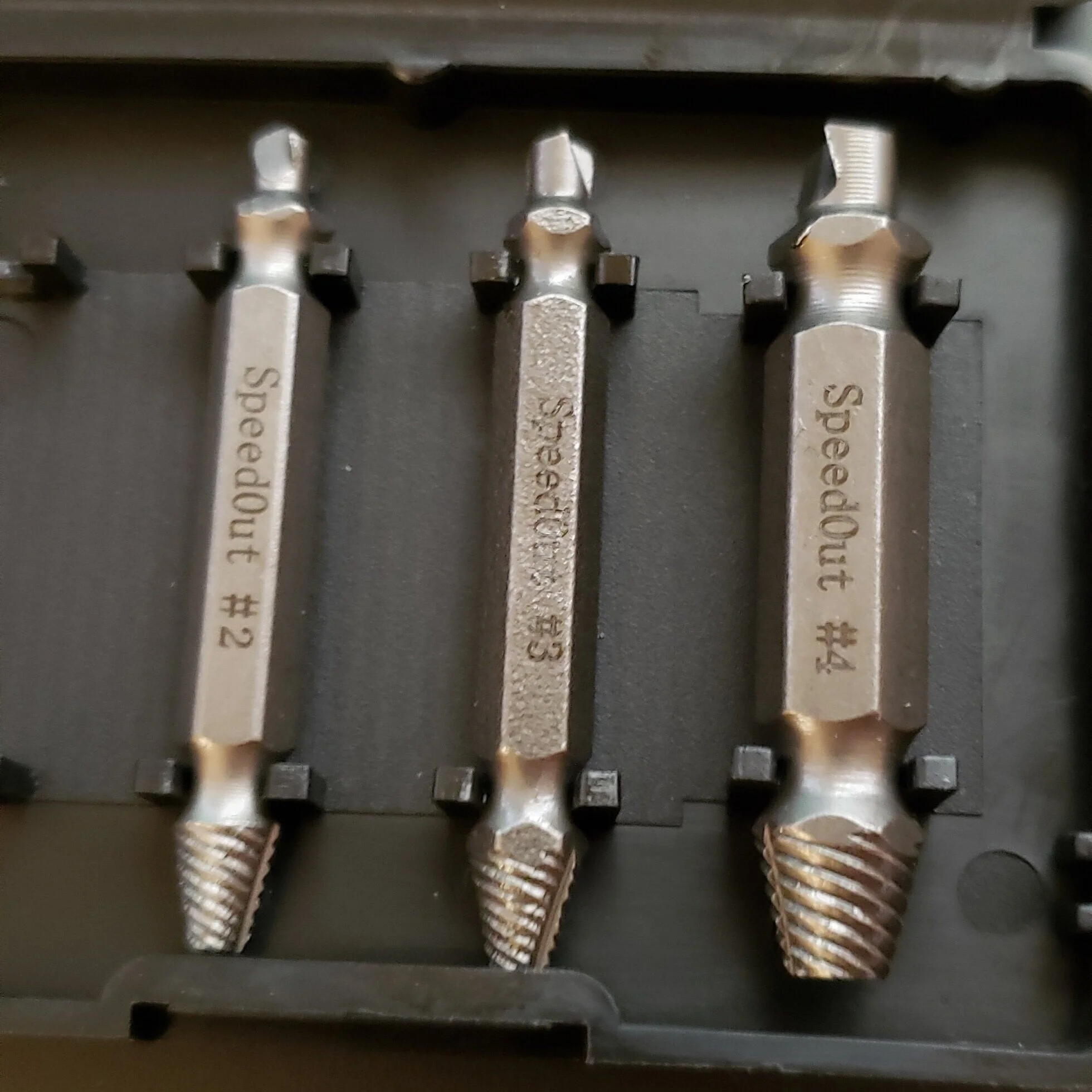
These extractor bits are worth their weight in gold; a metal which is rather soft in its pure form, yet seemingly much less malleable than whatever was used to cast the set screws I shredded
Following this the disassembly became much easier, though it still required some patience. Extracting 2 axes of machined metal covered in greasy bearings means a lot of soft tapping with a rubber mallet before they are willing to come off, and even more after that to remove the individual ball bearings and gears from the combined stack. Ed goes over each step of this in the instructional video in detail, including pitfalls to avoid, so even if all of this sounds complicated as you read it here, it is much less so after watching the video.

An exploded view of the components inside the Right Ascension housing, shown in one of multiple diagrams included in the Deep Space Products kit
Once everything is disassembled its time for cleaning. Many of the components require little more than a simple wipe down, but the gears themselves require more attention. A citrus-based degreaser is recommended (though not included in the kit) as opposed to harsher cleaning methods like Mineral Spirits. This was the end of the first day of work for me.

The end of day 1: a mount in pieces and the Tools aisle of a Home Depot
Day 2: Modifications & Reassembly
Now begins the modifications. The Ring Gear first needed to be sanded down to a slightly smaller diameter. The kit includes extremely fine grit sandpaper as well as polishing compound to shine it back up. The goal is to enable the ring gears to better fit into their respective housings without easily becoming stuck. Once everything is lubricated and reassembled this should allow easier freedom of movement.

The RA and Dec gears, one polished and the other only sanded
The other modifications are replacement of the stock spacers (small rings of plastic placed between some of the ball bearings to reduce contact) with Teflon spacers and exchanging a couple of the metal ball bearings on each side of the worm gears with ceramic replacements. While the latter replacement is a simple process of tossing out the old bearings and installing new ones from the kit in their place, finding the appropriate size of spacer (the kit provides them in 3 thicknesses) requires use of a caliper. Various sections of the gears and housing are measured (which requires a partial and temporary reassembly), and these measurements are divided and subtracted from each other in various ways in order to determine how much space is needed to slightly lift the moving axes away from the lower housing as well as ensuring that some of the gears are properly meshing together. The instructional video is easy to follow through this process and the included PDFs have a worksheet which has lines for recording the measurement as well as written instructions on the required math.
Reassembly of the Right Ascension housing. The mount moves back and forth by using motors to drive the worm gear seen at the top of the lower section, and as the worm gear rotates it slides itself around the large ring gear which is locked into place with the clutch lever in the lower left
With the proper spacers in place, and after applying a new layer of grease to the bearings, gears, and some of the housing surfaces, the mount is ready for reassembly. This is much easier than the initial disassembly since gravity is generally a little more helpful in settling the bearings into place, plus the ring gears are now slightly smaller. During this process a couple gears and set screws may need some alignment adjustments, but this is more tedious than difficult. Unfortunately after reassembly was complete and I was able to test the free movement of the axes with unlocked clutches, I still found the improvement to be somewhat lacking.
The Right Ascension movement after hypertuning was much better than before, but was still more restricted than I hoped.
While the movement of both axis was smoother than before, it did not have some of the seemingly effortless rotation that I had seen in the few examples I could find online. I suspected I had either applied too much lubricant during reassembly or had insufficiently sanded down the ring gear, either of which could cause excessive friction. Fortunately, correcting both of these assumed problems would not mean another complete teardown since I only needed to entirely remove a select few components.
Day 3: Fine Tuning
I spent a couple hours on the third day re-sanding and re-polishing the ring gears of both axes and then reassembling the components, all the while wiping down the ring gear between fitting tests which reduced the overall amount of lubricate in the housing. When I removed the ring gears during this process I noticed some darker parallel lines circling their outer edges which I think supports my idea that I had not sanded them down far enough. I also decided to replace one of the Teflon spacers with a slightly thicker option (the math indicated I could use small or medium spacer, so I swapped to a medium), and I think the result in the video below speaks for itself. The RA axis of the mount moves with ease, yet when the clutches are locked and the motors powered the mount sounds seemingly identical to pre-hypertuning alterations. I didn’t show the Declination movement in the video below, but even the minor unbalanced weight of the clutch lever and the dovetail knobs prompt it to slowly rotate.
The CGEM’s Right Ascension movement is much smoother now
Day 4: Back Under the Stars
The final Saturday night before my return to work proved clear enough for a field test. Unclutched movement seems good, but until it was brought back under the night sky it was hard to say whether my anecdotal evidence of “I dunno, I guess the gears sound OK” was indicative of success. Loading the counterweight and telescope (in that order) onto the mount while it was still inside and having it slew to an imaginary target did not reveal any obvious issues, so the last step was to actually polar align and lock my autoguider onto a star.
I must have done something right because I could see an immediate difference in the GoTo precision when slewing to a target. My capture software AstrophotographyTool acts like a control tower for all my hardware, and my usual routine for centering a target is to have APT command the telescope to slew to a given position, then have the camera capture an image and plate-solve it to verify the telescope’s actual position. If the target is found to be off-center after plate solving, APT will command the mount to correct for this and then repeat the process until the target is placed within a given margin of error. Before hypertuning this process usually required 3 attempts, but now centers objects in just two.
Autoguiding, however, was less satisfying. Removing the backlash entirely would not be possible in a budget mount like this, but I still could not see any significant reduction at first. I started eliminating what problems I could find, first ensuring the guidescope itself was refocused and aligned to the main imaging optic, then loosening the Dec motor and forcing it incrementally closer to the spur gears to reduce space between the teeth. Following this, and once the patchwork of mid-level clouds had dispersed, I ran several iterations of PHD2’s Guiding Assistant which analyzed the observed backlash via star drift. This combined effort seemed to improve performance, though the graphs still made me grimace a little.

Tempering expectations can be important, especially given the temptation to endlessly fiddle with some adjustment screw in pursuit of a nonexistent perfection. With that in mind, and noting that I was a little into Sunday morning at this point, I ran a couple imaging tests. First was a series of 30-second exposures on the star Denebola. I had APT force a dither between every image and found it was taking longer than usual, nearly 45-60 seconds, longer than the 15-20” to which I was accustomed. I’m not sure what to make of that or what could cause it (especially considering the improved accuracy of the slewing would indicate it can move and settle faster) but it is hardly a deal breaker.
My second test was to take a 10-minute exposure on the same area and I was pleased to find no stars had any apparent elongation. Even if they had it would not a major problem since my typical photos use a maximum exposure of 5 minutes, and the continually changing atmospheric conditions I typically suffer make sharply resolved stars a malleable concept either way.
The final performance of guiding. The lower graph ooks messy close up, but the Y axis is at +/-8. Overall the backlash is reduced and the RMS error is much smaller than before

1x600” Luminance on Denebola. While the stars in the corner are a little smeared, this is caused by my optics, not tracking
Final Review and Consideration of the Future
Even if the Hypertuning had not been as apparently successful I think I would still be satisfied with the improvements. The disassembly alone was a learning and confidence-building experience and now that the process is done I have a much better understanding of which physical components and respective adjustment screws are able to tune out any future issues, or at least reduce them to manageable levels. Prior to this I had a vague idea that the mount used some combination of gears and magic to drive itself coupled with an unspoken assumption that adjusting any kind of mechanics in the mount would require some kind of precision measurements, lest I irrevocably harm the tracking performance through ignorant tinkering. As it turns out, the only “precision measurement” required during the field to clean much of the Declination backlash was a slight turn of a screw driver to force the Declination motor gear a little closer to its neighbor. I suppose I should have expected that considering how much of Astronomy uses estimates.
Anyone considering this process, again admitting that I have no idea how other mounts are broken down, should not consider it to be a Herculean task. While the entire project may have totaled about 25 hours of work on my end this was more due to the tedious nature of cleaning, sanding, and polishing various components as well as periodically rewinding the instructional video by a couple minutes to verify I was completing some part of the procedure correctly (plus waiting for the test exposures to complete). Despite the tedium, I would not describe the process as technically complicated or confusing at any point. You just have to be brave enough to start the disassembly.
However, anyone considering similar modifications to their own mount should realize the improvements from Hypertuning will only go so far and other strategies like proper balance, good polar alignment, and periodic error correction should still be in use along side it. Either way, the CGEM is not going to be the last mount I buy. As expensive as it seemed it is barely a mid-tier budget mount, but for my forgivingly low focal length an expensive Paramount or 10Micron would offer no significant improvement - especially under the typically substandard atmospheric conditions of Kansas sky. I still intend to eventually upgrade to a premium tracking mount (pending a little more government stimulus), because I think Ed himself put it best when he told me, “The key is to get the mount that doesn’t need this kind of work at all.”